
For timber surfaces with the "Constant" thickness type, the crack factor kcr and thus the negative influence of cracks on the shear capacity is taken into account.

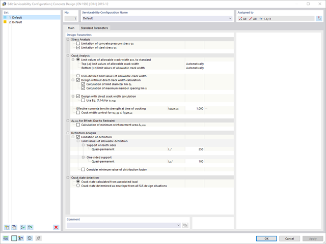
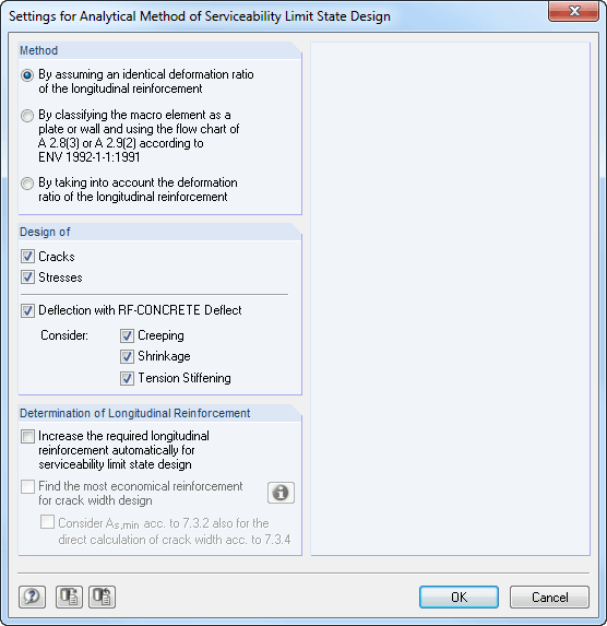
Various design parameters of the cross-sections can be adjusted in the serviceability limit state configuration. The applied cross-section condition for the deformation and crack width analysis can be controlled there.
For this, the following settings can be activated:
- Crack state calculated from associated load
- Crack state determined as an envelope from all SLS design situations
- Cracked state of cross-section - independent of load

Did you know? In contrast to other material models, the stress-strain diagram for this material model is not antimetric to the origin. You can use this material model to simulate the behavior of steel fiber-reinforced concrete, for example. Find detailed information about modeling steel fiber-reinforced concrete in the technical article about Determining the material properties of steel-fiber-reinforced concrete.
In this material model, the isotropic stiffness is reduced with a scalar damage parameter. This damage parameter is determined from the stress curve defined in the Diagram. The direction of the principal stresses is not taken into account. Rather, the damage occurs in the direction of the equivalent strain, which also covers the third direction perpendicular to the plane. The tension and compression area of the stress tensor is treated separately. In this case, different damage parameters apply.
The "Reference element size" controls how the strain in the crack area is scaled to the length of the element. With the default value zero, no scaling is performed. Thus, the material behavior of the steel fiber concrete is modeled realistically.
Find more information about the theoretical background of the "Isotropic Damage" material model in the technical article describing the Nonlinear Material Model Damage.

You determine the deformation for members and surfaces, taking into account the cracked (state II) or non-cracked (state I) reinforced concrete cross-section. When determining the stiffness, you can consider "tension stiffening" between the cracks according to the design standard used.

Was your design successful? Then just sit back and relax. You benefit from the numerous functions in RFEM also here. The program gives you the maximum stresses of the masonry surfaces, whereby you can display the results in detail at each FE mesh point.
Moreover, you can insert sections in order to carry out a detailed evaluation of the individual areas. Use the display of the yield areas to estimate the cracks in the masonry.
- Deformation analyses of reinforced concrete surfaces without or with cracks (state II) by applying the approximation method (for example, deformation analysis according to ACI 318-19, 24.3.2.5 or EN 1992‑1‑1, Cl. 7.4.3 )
- Tension stiffening of concrete applied between cracks
- Optional consideration of creep and shrinkage
- Graphical representation of results integrated in RFEM, such as deformation or sag of a flat slab
- Clear numerical result display in the detail dialog box
- Complete integration of results in the RFEM printout report
Are you looking for a deformation calculation? Check the Serviceability Configuration, where it can be activated. You can also control the consideration of long-term effects (creep and shrinkage) and tension stiffening between cracks in the dialog box above. The creep coefficient and shrinkage strain are calculated using the specified input parameters, or you can define them individually.
Furthermore, you can specify the deformation limit value individually for each structural component. The max. deformation is defined as the allowable limit value. In addition, you have to specify whether you want to use the undeformed or the deformed system for the design check.

The standards already specify the approximation methods (for example, deformation calculation according to EN 1992‑1‑1, 7.4.3, or ACI 318‑19, 24.3.2.5) that you need for your deformation calculation. In this case, the so-called effective stiffnesses are calculated in the finite elements in accordance with the existing limit state with / without cracks. You can then use these effective stiffnesses to determine the deformations by means of another FEM calculation.
Consider a reinforced concrete cross-section for the calculation of the effective stiffnesses of the finite elements. Based on the internal forces determined for the serviceability limit state in RFEM, you can classify the reinforced concrete cross-section as "cracked" or "uncracked". Do you consider the effect of the concrete between the cracks? In this case, this is done by means of a distribution coefficient (for example, according to EN 1992‑1‑1, Eq. 7.19, or ACI 318‑19, 24.3.2.5). You can assume the material behavior for the concrete to be linear-elastic in the compression and tension zone until reaching the concrete tensile strength. This procedure is sufficiently precise for the serviceability limit state.
When determining the effective stiffnesses, you can take into accout the creep and shrinkage at the "cross-section level." You don't need to consider the influence of shrinkage and creep in statically indeterminate systems in this approximation method (for example, tensile forces from shrinkage strain in systems restrained on all sides are not determined and have to be considered separately). In summary, the deformation calculation is carried out in two steps:
- Calculation of effective stiffnesses of the reinforced concrete cross-section assuming linear-elastic conditions
- Calculation of the deformation using the effective stiffnesses with FEM
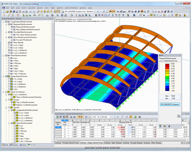
RF-CONCRETE Surfaces
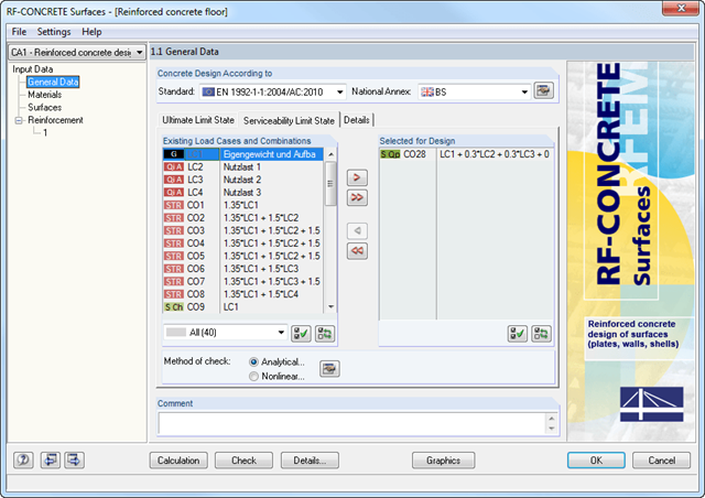
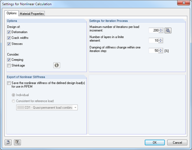
The nonlinear calculation is activated by selecting the design method of the serviceability limit state. You can individually select the analyses to be performed as well as the stress-strain diagrams for concrete and reinforcing steel. The iteration process can be influenced by these control parameters: convergence accuracy, maximum number of iterations, arrangement of layers over cross-section depth, and damping factor.
You can set the limit values in the serviceability limit state individually for each surface or surface group. Allowable limit values are defined by the maximum deformation, the maximum stresses, or the maximum crack widths. The definition of the maximum deformation requires additional specification as to whether the non-deformed or the deformed system should be used for the design.
RF-CONCRETE Members
The nonlinear calculation can be applied to the ultimate and the serviceability limit state designs. In addition, you can specify the concrete tensile strength or the tension stiffening between the cracks. The iteration process can be influenced by these control parameters: convergence accuracy, maximum number of iterations, and damping factor.
Before the calculation starts, you should check the input data using the program function. Then, the CONCRETE add‑on module searches the results of relevant load cases, load as well as result combinations. If these cannot be found, RSTAB starts the calculation to determine the required internal forces.
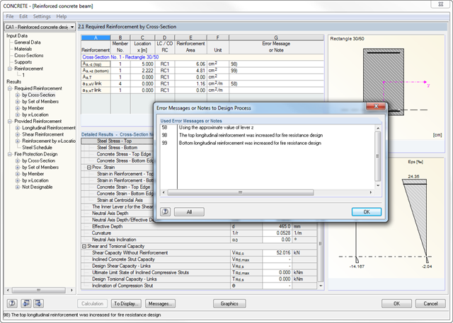
Considering the selected design standard, the required reinforcement areas of the longitudinal and the shear reinforcement as well as the corresponding intermediate results are calculated. If the longitudinal reinforcement determined by the ultimate limit state design is not sufficient for the design of the maximum crack width, it is possible to increase the reinforcement automatically until the defined limit value is reached.
The design of potentially unstable structural components is possible using a nonlinear calculation. According to a respective standard, different approaches are available.
The fire resistance design is performed according to a simplified calculation method in compliance with EN 1992‑1‑2, 4.2. The module uses the zone method mentioned in Annex B2. Furthermore, you can consider the thermal strains in the longitudinal direction and the thermal precamber additionally arising from asymmetrical effects of fire.
The deformation analysis according to the approximation method defined in standards (for example, deformation analysis according to EN 1992‑1‑1, 7.4.3) applies to the calculation of "effective stiffnesses" in the finite elements in accordance with the existing limit state of the concrete with or without cracks. These stiffnesses are used to determine the surface deformation by repeated FEM calculation.
The effective stiffness calculation of finite elements takes into account a reinforced concrete cross-section. Based on the internal forces determined for the serviceability limit state in RFEM, the program classifies the reinforced concrete cross-section as 'cracked' or 'uncracked'. If the tension stiffening at a section should be considered as well, a distribution coefficient (according to EN 1992-1-1, Eq. 7.19, for example) is used. The material behavior for the concrete is assumed to be linear-elastic in the compression and tension zone until the concrete tensile strength is reached. This is reached exactly in the serviceability limit state.
When determining the effective stiffnesses, creep and shrinkage are taken into account at the "cross-section level". The influence of shrinkage and creep in statically indeterminate systems is not taken into account in this approximation method (for example, tensile forces from shrinkage strain in systems restrained on all sides are not determined and must be considered separately). In summary, RF-CONCRETE Deflect calculates deformations in two steps:
- Calculation of effective stiffnesses of the reinforced concrete cross-section assuming linear-elastic conditions
- Calculation of the deformation using the effective stiffnesses with FEM
- Import of results from RSTAB
- Integrated material and cross-section library
- The module extension EC2 for RSTAB enables design of reinforced concrete according to EN 1992-1-1 (Eurocode 2) and the following National Annexes:
-
 DIN EN 1992-1-1/NA/A1:2015-12 (Germany)
 -
 ÖNORM B 1992-1-1:2018-01 (Austria)
 -
 Belgium NBN EN 1992-1-1 ANB:2010 for design at normal temperature, and NBN EN 1992-1-2 ANB:2010 for fire resistance design (Belgium)
 -
 BDS EN 1992-1-1:2005/NA:2011 (Bulgaria)
 -
 EN 1992-1-1 DK NA:2013 (Denmark)
 -
 NF EN 1992-1-1/NA:2016-03 (France)
 -
 SFS EN 1992-1-1/NA:2007-10 (Finland)
 -
 UNI EN 1992-1-1/NA:2007-07 (Italy)
 -
 LVS EN 1992-1-1:2005/NA:2014 (Latvia)
 -
 LST EN 1992-1-1:2005/NA:2011 (Lithuania)
 -
 MS EN 1992-1-1:2010 (Malaysia)
 -
 NEN-EN 1992-1-1+C2:2011/NB:2016 (Netherlands)
 - NS EN 1992-1 -1:2004-NA:2008 (Norway)
-
 PN EN 1992-1-1/NA:2010 (Poland)
 -
 NP EN 1992-1-1/NA:2010-02 (Portugal)
 -
 SR EN 1992-1-1:2004/NA:2008 (Romania)
 -
 SS EN 1992-1-1/NA:2008 (Sweden)
 -
 SS EN 1992-1-1/NA:2008-06 (Singapore)
 -
 STN EN 1992-1-1/NA:2008-06 (Slovakia)
 -
 SIST EN 1992-1-1:2005/A101:2006 (Slovenia)
 -
 UNE EN 1992-1-1/NA:2013 (Spain)
 -
 CSN EN 1992-1-1/NA:2016-05 (Czech Republic)
 -
 BS EN 1992-1-1:2004/NA:2005 (United Kingdom)
 -
 CPM 1992-1-1:2009 (Belarus)
 -
 CYS EN 1992-1-1:2004/NA:2009 (Cyprus)
-
- In addition to the National Annexes (NA) listed above, you can also define a specific NA, applying user‑defined limit values and parameters.
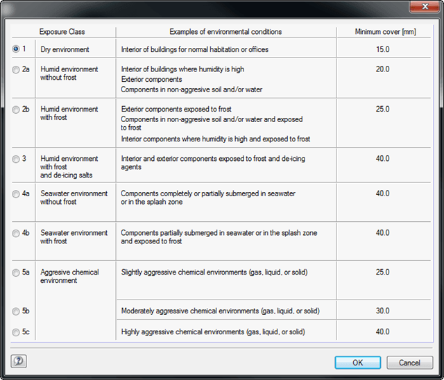
- Optional presetting of partial safety factors, reduction factors, neutral axis depth limitation, material properties, and concrete cover
- Determination of longitudinal, shear, and torsional reinforcement
- Design of tapered members
- Cross‑section optimization
- Representation of minimum and compression reinforcement
- Determination of editable reinforcement proposal
- Crack width analysis with optional increase of the required reinforcement in order to keep the defined limit values of the crack width analysis
- Nonlinear calculation with consideration of cracked cross‑sections (for EN 1992‑1‑1:2004 and DIN 1045‑1:2008)
- Considering tension stiffening
- Considering creep and shrinkage
- Deformations in cracked sections (state II)
- Graphical representation of all result diagrams
- Fire resistance design according to the simplified method (zone method) according to EN 1992‑1‑2 for rectangular and circular cross‑sections. Thus, fire resistance design of brackets is possible as well.
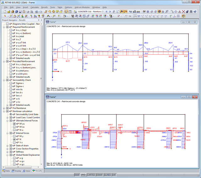
After the calculation, the module shows clearly arranged tables listing the required reinforcement and the results of the serviceability limit state design. All intermediate values are included in a comprehensible manner. In addition to the tables, current stresses and strains in a cross‑section are represented graphically.
The reinforcement proposals of the longitudinal and the shear reinforcement, including sketches, are documented in accordance with current practice. It is possible to edit the reinforcement proposal and to adjust, for example, the number of members and the anchorage. The modifications will be updated automatically.
A concrete cross‑section, including reinforcement, can be visualized in a 3D rendering. This way, the program provides an optimal documentation option to create reinforcement drawings, including steel schedule.
Crack width analyzes are performed using the selected reinforcement of internal forces in the serviceability limit state. The result output covers steel stresses, the minimum reinforcement, limit diameters, and the maximum bar spacing, as well as crack spacing and the maximum crack widths.
As a result of the nonlinear calculation, there are the ultimate limit states of the cross‑section with defined reinforcement (determined linear elastically) as well as effective deflections of the member considering stiffness in cracked state.
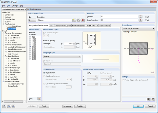
After opening the program, you can define the standard and method according to which the design is performed. The ultimate and serviceability limit states can be designed according to the linear and nonlinear calculation methods. Load cases, load combinations or result combinations are then assigned to different calculation types. In other input windows, you can define materials and cross‑sections. In addition, it is possible to assign parameters for creep and shrinkage. Creep and shrinkage coefficients are directly adjusted, depending on the age of the concrete.
Support geometry is determined by means of design‑relevant data such as support widths and types (direct, monolithic, end, or intermediate support) and redistribution of moments as well as shear force and moment reduction. CONCRETE recognizes the support types from the RSTAB model automatically.
A segmented window includes the specific reinforcement data such as diameters, the concrete cover and curtailment type of reinforcements, number of layers, cutting ability of links, and the anchorage type. In the case of the fire resistance design, it is necessary to define the fire resistance class, the fire‑related material properties, and the cross-section side exposed to fire. Members and sets of members can be summarized in special 'reinforcement groups', each with different design parameters.
You can adjust the limit value of the maximum crack width in the case of crack width analysis. The geometry of tapers is to be determined additionally for the reinforcement.
When determining internal forces, you can choose between calculation method 1 (uncracked over entire beam length) and calculation method 2 (crack formation over internal columns).
In both cases, it is possible to consider a constant effective width of the concrete slab over the entire span according to ENV 1994-1-1, 4.2.2.1 (1) and a redistribution of the moments. Internal forces for the design of shear connectors can only be determined by the elastic calculation of internal forces using the RSTAB analysis core (no RSTAB license is required).
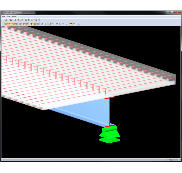
The calculation performs fully automatic determination of the effective cross-section properties at the respective points of time, considering creep and shrinkage. In the RSTAB user interface, the structural models are created as a member structure, including all boundary conditions and loading. This way, reliable calculation of the internal forces with the effective cross-section properties is ensured.
Results are displayed in result tables sorted by required designs. Clear arrangement of the results allows for easy orientation and evaluation.
Ultimate Limit State Design:
- Bending and shear force resistance with interaction
- Partial shear connecting of ductile and non-ductile connecting elements
- Determination of required shear connectors and their distribution
- Design of longitudinal shear force resistance
- Design of connection with shear connectors and of connector perimeter
- Results of governing support reactions for construction and composite stage, including loads of construction supports
- Lateral-torsional buckling analysis (for continuous beams and cantilevered girders)
- Check of cross-section classes as well as of plastic and elastic cross-section properties
Serviceability limit state design:
- Deflection Analysis
- Deformations and initial pre-cambering determined with ideal cross-section properties from creep and shrinkage
- Analysis of natural frequencies
- Crack width analysis
- Determination of support forces
All data are documented in a clearly arranged printout report, including graphics. In case of any modification, the printout report is updated automatically. COMPOSITE-BEAM is a stand-alone program and does not require the RSTAB license.
RF-CONCRETE Surfaces:
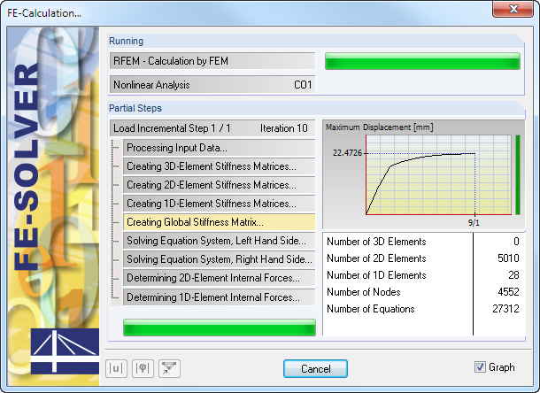
The nonlinear deformation analysis is performed by an iterative process considering the stiffness in cracked and non-cracked sections. The nonlinear reinforced concrete modeling requires definition of material properties varying across the surface thickness. Therefore, a finite element is divided into a certain number of steel and concrete layers in order to determine the cross-section depth.
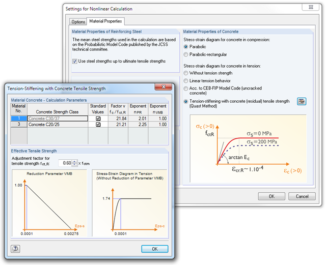
The mean steel strengths used in the calculation are based on the 'Probabilistic Model Code' published by the JCSS technical committee. It is up to the user whether the steel strength is applied up to the ultimate tensile strength (increasing branch in the plastic area). Regarding material properties, it is possible to control the stress-strain diagram of the compressive and tensile strength. For the concrete compressive strength, you can select a parabolic or a parabolic-rectangular stress-strain diagram. On the tension side of the concrete, it is possible to deactivate the tensile strength as well as to apply a linear-elastic diagram, a diagram according to the CEB-FIB model code 90:1993, and concrete residual tensile strength considering the tension stiffening between the cracks.
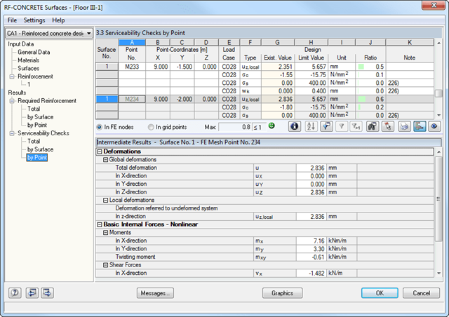
Furthermore, you can specify which result values should be displayed after the nonlinear calculation at the serviceability limit state:
- Deformations (global, local based on non-/deformed system)
- Crack widths, depths, and spacing of the top and bottom sides in principal directions I and II
- Stresses of the concrete (stress and strain in principal direction I and II) and of the reinforcement (strain, area, profile, cover, and direction in each reinforcement direction)
RF-CONCRETE Members:
The nonlinear deformation analysis of beam structures is performed by an iterative process considering the stiffness in cracked and non-cracked sections. The material properties of concrete and reinforcing steel used in the nonlinear calculation are selected according to a limit state. The contribution of the concrete tensile strength between the cracks (tension stiffening) can be applied either by means of a modified stress-strain diagram of the reinforcing steel, or by applying a residual concrete tensile strength.
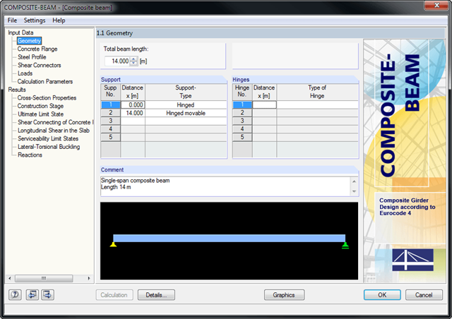
- Single-span and continuous beams with definable boundary conditions
- Automatic determination of effective cross-sections
- Free arrangement of construction supports for construction stage
- Freely definable concentrated, distributed, and trapezoidal loads as fixed loads with specification of concrete age during loading
- Freely definable construction loads as well as moving construction loads
- Automatic load combination
- Calculation of cross-section properties according to Method 1 or 2
- Calculation of elastic internal forces with RSTAB
- Redistribution of Moments
- Design of bending and shear force resistance with interaction
- Determination of required shear connectors and their distribution
- Design of longitudinal shear force resistance
- Results of governing support reactions for construction and composite stage, including loads of construction supports
- Lateral-torsional buckling analysis
- Analysis for limitation of crack widths
- Design of natural frequency
The deformation analysis with RF-CONCRETE Deflect can be activated in the settings for the analytical serviceability limit state design in the RF-CONCRETE Surfaces module. Consideration of long-term effects (creep and shrinkage) and tension stiffening between cracks can also be managed in the dialog box above. The creep coefficient and shrinkage strain are calculated using the specified input parameters or defined individually.
You can specify the deformation limit value individually for each surface or for an entire surface group. The max. deformation is defined as the allowable limit value. In addition, you have to specify whether the undeformed or the deformed system is to be used for the design check.
- Deformation analyses of reinforced concrete surfaces without or with cracks (state II) by applying the approximation method (for example, deformation analysis according to EN 1992-1-1, Cl. 7.4.3 )
- Tension stiffening of concrete applied between cracks
- Optional consideration of creep and shrinkage
- Graphical representation of results integrated in RFEM; for example, deformation or sag of a flat slab
- Numerical results clearly arranged in tables and graphical display of the results in the model
- Complete integration of results in the RFEM printout report
- Iterative nonlinear calculation of deformations for beam and plate structures consisting of reinforced concrete by determining the respective element stiffness subjected to the defined loads
- Deformation analyses of cracked reinforced concrete surfaces (state II)
- General nonlinear stability analysis of compression members made of reinforced concrete; for example, according to EN 1992-1-1, 5.8.6
- Tension stiffening of concrete applied between cracks
- Numerous National Annexes available for the design according to Eurocode 2 (EN 1992-1-1:2004 + A1:2014, see EC2 for RFEM)
- Optional consideration of long-term influences such as creep or shrinkage
- Nonlinear calculation of stresses in reinforcing steel and concrete
- Nonlinear calculation of crack widths
- Flexibility due to detailed setting options for basis and extent of calculations
- Graphical representation of results integrated in RFEM; for example, deformation or sag of a flat slab made of reinforced concrete
- Numerical results clearly arranged in tables and graphical display of the results in the model
- Complete integration of results in the RFEM printout report
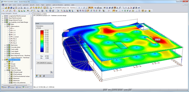
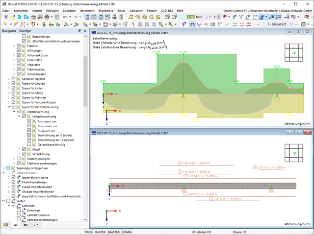
After the calculation, the module shows clearly arranged tables listing the results of the nonlinear calculation. All intermediate values are included in a comprehensible manner. Graphical representation of design ratios, deformations, concrete and reinforcing steel stresses, crack widths, crack depths, and crack spacing in RFEM facilitates a quick overview of critical or cracked areas.
Error messages or remarks concerning the calculation help you find design problems. Since the design results are displayed by surface or by point including all intermediate results, you can retrace all details of the calculation.
Due to the optional export of input or result tables to MS Excel, the data remain available for further use in other programs. The complete integration of results in the RFEM printout report guarantees verifiable structural design.
The material library already includes Swiss types of concrete and reinforcing steel available for design. However, you can always define other materials for the design according to SIA 262. The program performs the ultimate and the serviceability limit state design.
The crack width analysis can be performed using the design of Sigmas,adm, rebar spacing sL, or a direct calculation of crack widths according to the technical documentation D0182. Depending on the selected concrete type, the program determines the limit value Sigmas,adm according to D0182, Eq. 10.13; the upper limit is set by the design criterion fsd.